Today I am writing about flow measurement techniques
The only direct way of measuring flow is to collect the total discharge in a calibrated container or in a weighing 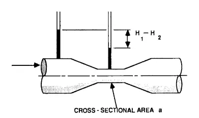 tank over a known period of time. This technique is clearly not very practicable for most situations, so that some indirect means of flow measurement is usually necessary. This will involve the use of a gauging structure, velocity measurements in a known cross-section, or dilution gauging.
Gauging:
A common and accurate method of flow measurement is to pass the flow through or over a structure which has a known head-discharge relationship. For closed pipes or conduits running under pressure, venturi meters or orifice plates are the normal means of flow measurement. These rely on using the differential pressure across the device to determine the flow. Thus for a venturi meter the discharge is given by
Q = C a [ 2g (H1 – H2) ] 0.5
Where
Q = flow
C = discharge coefficient
a = cross-sectional area of throat
g = acceleration due to gravity
H1 – H2 = pressure difference between inlet and throat
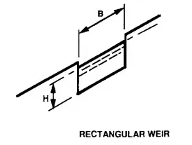
For open channels, flows can be determined using venturi flumes, sharp-edged rectangular or vee weir plates, broad crested weirs or triangular profile weirs. The basic equations for thin plate weirs, ignoring approach velocity effects, are
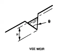
Vee notch
Q=0.53 tan (θ/2) (2g)0.5 H2.5
Rectangular notch
Q = 0.67 B (2g)0.5 H1.5
Where
θ = angle subtended by notch
H = head over notch
B = width of rectangular notch
Measurement of head is usually by means of a float in a stilling well upstream of the structure or with an ultrasonic level detector. Gauging structures can be costly to construct and can cause undesirable restrictions to the flow, so that in many circumstances they may not be appropriate and one of the other flow-gauging techniques must be used.
Velocity measurements:
Since discharge is the product of velocity and cross-sectional area, it is clearly possible to determine discharge in a channel or pipe by measuring the velocity in a known cross-section. In practice the situation is complicated by the fact that velocity is not constant in a flow and in 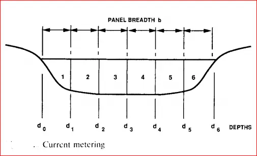 natural channels the cross-section is likely to be irregular. A simple approximation is to take the velocity measured at 0.6 depth from the surface as being the mean velocity of flow. For small channels a float suitably ballasted can be used to give an indication of the 0.6 depth velocity but for more accurate measurements a current meter must be employed. This is a propeller or bucket wheel device which is held in the flow and caused to rotate by movement of water past it. Visual or electronic indications are given after a known number of revolutions and these can be related to velocity by means of a tank calibration. Accuracy of measurements is helped by dividing the section into a number of panels, as shown.
Q = ∑ [(dn + dn+1) / 2] [(Vn + Vn+1) / 2] b
A newer technique for measuring mean velocity which is becoming increasingly popular employs ultrasonic beams which are transmitted at an angle across the channel and reflected back to a transmitter/receiver. Discontinuities in the flow reflect and attenuate the sound waves so that the pulses travelling in the two directions have slightly different timings due to the velocity of the water.